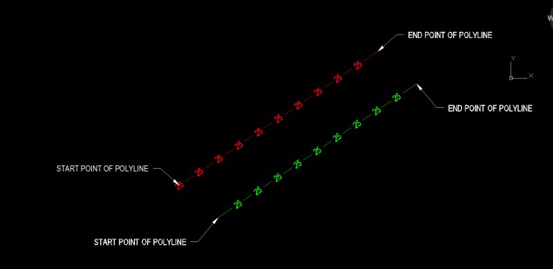
Contour Elevations at Intervals with Labels elevates contour polylines and/or labels them. Uses an exploded block for labeling so you can customize label as needed. Uses fields for labeling if you choose. Saves to (setcfg) to remember settings between sessions. Saves to a single global variable during a session. Lets you ignore Interval, Label Precision, Label Spacing, Temporary Color. All AutoCAD variants except LT: The LISP utility CHELEV (command CHELEV) can easily assign proper elevation (Z) to a set of contours. Just pick two points connecting a line climbing across the contour set and specify the bottom elevation and the contour step. The CHELEV.LSP file can be downloaded from CAD Studio. Load it into AutoCAD with APPLOAD.
Sep 15, 2005 - AutoLISP can form an intermediate contour that assumes a linear. Judas san pedro serial killer wiki. LSP files from Cadalyst's CAD Tips site and save them in AutoCAD's. This really shows the great convenience of using the more modern approach to LISP.

ConTour Lisp Notes USE AT YOUR OWN RISK! CTL Notes This routine creates 3D contour lines from 3D points. It was written for Autocad 2000, so there's no guarantee it will work for your version. Supports any version. Download a free trial here. See Lisp Notes below ------------------------------------- Unzip files to /support directory or any directory in program search path. Type (load'ctl_c1') at the command prompt to load routine.
Type 'CTL' at the command prompt for option list. Command: CTL 1. Read/Write CSV Point File. Draw Triangulated Surface. Draw Contour Lines. Color Contours/Objects. Annotate Contours.

Cross Sections from Contours. Area Calculations. Swap Triangle Pairs.
Samsung easy printer manager mac os 10 14. Option 1 imports any xyz comma separated point file onto layer 'CTL_PNT' or writes any selected points on layer 'CTL_PNT' or 'CTL_PTMP' to a comma separated point file and deletes all selected points from the drawing. If you read a file, it will erase any existing points on layer 'CTL_PTMP' and change any existing points on layer 'CTL_PNT' to layer 'CTL_PTMP. The point files can have white spaces, but no tab characters or blank lines.
Option 2 creates a triangulated surface from all points found on layer 'CTL_PNT'. It will prompt you to check for duplicate points. It can take a while to check if you have thousands of points, but the program will hang if you don't delete them first. Option 2 calculates all triangle points and takes an average of all long side horizontal lengths. You can ignore this value and create all triangles, or enter a factor to delete any triangle with sides longer than the average times a factor from 1.5 to 5.0. You can either ignore this option or use it to delete most of the extraneous triangle faces that shouldn't be there. It always deletes any previous triangles, so can keep trying different factors to get the surface the the way you want. If you need to change a space separated point file to a comma separated file, try one of these command line programs. 32 bit version (142,848 bytes) or 16 bit version (18,600 bytes) (8 char file names only.) Option 3 creates contours by drawing plines thru each triangle surface on temporary layers.
It selects all lines on each elevation, joins them and asks if you want to create spline fit curves. Spline curves take up a huge amount of drawing space and lose accuracy on sharp corners if enough points are not supplied. If successfully joined/splined, it changes each contour to layer CTL_CONT and deletes all temporary layers. Option 4 switches to a front view, uses the latest contour spacing with the left and right limits to select and color contours.
Keil professional for c51 v812 keygen by edge. It uses a crossing window to select the contours, so make sure your drawing limits don't exceed the limits of the objects by some huge distance. If you open a drawing and run this routine before you create any contours, it will check if there's any surface on layer CTL_TIN to find hi and low points. If not, it will ask you to supply both numbers in integer values.
Anything above and below what you're coloring will work. It then asks you to pick an entity on the layer you want to color and the vertical spacing you want to use. Option 5 annotates by picking a point on any contour line. How to unlock itel mobile password. It will prompt to either break the contour line or place the text above the line. Drag the cursor to the right to align the text. It will prompt you for a text size so you should check for clearance between contours.
It reads the elevation from the pick point so you don't have to type anything. The text is written at that elevation on layer 'CTL_CTXT'. If you colored the contours with the Major/Minor option, the major lines should already be on even elevations. 50 unit contours spaced at 5 show up above. A 20 unit contour spaced at 5 will be even 100 units or 40 units spaced at 5 will be 200 unit elevations. Option 6 creates cross sections from contours on layer CTL_CONT. You need to draw a 'LINE' over the contours to section.
It searches along the section 'LINE' with a crossing fence and will prompt you for a fence distance. If the fence is larger than the smallest contour spacing, you could miss some contour points.
Free Lisp Autocad
It will prompt for a starting station if your sections are equally spaced and you want to add stations to your profiles. It only takes integer values. You can always overwrite the default station number and reset the forward spacings. The profiles are drawn left to right from the direction the section line was drawn. If you get it backwards, you can either rotate the section line 180 degrees or just mirror the profile since it's center based. Hotspot shield premium apk download apkpure.
1JanAutocad Contour Lisp
Mar 29, 2012 - This routine is helpful if you have overlapping objects that form a closed area and you would like to combine them into one overall closed object.
Contour Elevation Label Contour Elevation Label This command can be used to simultaneously create elevation labels on a group of contour polylines at elevation. First the command starts with a dialog with the label options. Then to place the labels, pick two points crossing the contour polylines at the desired label location. The program will find all the contour polylines that intersect the picked line (defined by the two picked points) and will place labels at the intersection point of each contour. A second crossing line can be initiated immediately, so multiple areas can be quickly labeled while remaining in the command.
Near the top of the page, look for 'Graziano SAG 14 manuel', clicking on this phrase will take you to the list of downloads. It is a 14.2 MB pdf. Graziano SAG 14 (+ 17).
Alternatively, you can type P for Polyline at the Command prompt and select a polyline. Then the program finds all the intersections between the selected polyline and the contours and places labels at these intersections. The actual 'z' elevation of the contour line determines the label value. Label Layer specifies layer name for the contour labels that will be created. Label Style specifies the text style to be used for labels.

Horizontal Scale is used in conjunction with the Text Size Scaler to determine unit height of the contour labels. Text Size Scaler is a scaler that will be multiplied by the horizontal scale to set the actual text height of the labels in AutoCAD units. Integers controls how many digits to label to the left of the decimal.
Contour Lisp Autocad
For example, if all contours are in the 5000's, then setting for three digits would label the 5280 contour as 280. Decimals sets the decimal precision for the labels to be created. Label Position determines the label position in relation to the contour polyline. • On Contour centers the label on the contour line. • Above Contour places the label above the contour line. If this option is used, the options for Break Contours at Label and Draw Broken Segments become inactive. Ignore Zero Elevation Polylines enables the routine to filter out all entities with an elevation of zero.
Hide Drawing Under Labels activates a text wipeout feature that will create the appearance of trimmed segments at the contour label, even though the contour line is still fully intact. This feature provides the user with the best of both worlds; you have clean looking contour labels, yet the contour lines themselves remain contiguous. This feature will also hide other entities that are in the immediate vicinity of the contour label. Align Facing Uphill makes the label parallel to the contour and flips the label so that it reads facing uphill. Otherwise, the labels are made to face up relative to the current screen view.
When this option is on, the program prompts for a triangulation surface file that should match the surface the contours represent. Use Commas adds a comma into the labels for the thousands place such as '5,000' instead of '5000'. When Align Text with Contour is checked, contour elevation labels will be rotated to align with their respective contour lines. When Break Contours at Label is checked, the contour lines will be broken and trimmed at the label location for label visibility. When Draw Broken Segments is checked, segments of contours that are broken out for label visibility will be redrawn as independent segments. Specify the layer for these broken segments in the box to the right of this toggle.
Download Lisp Autocad

Label Contour Ends creates labels off the ends of the contours. Label By Distance places the labels by distance along the contour. The user is not prompted for screen picks of contour crossing when this option is used. • Interval sets the distance interval to be used between labels on each contour.
Contour Lisp Autocad 2019
When Draw Box Around Text is checked, a rectangle will be drawn around the elevation labels. The Offset Scaler controls the size of the rectangle. The Draw On Real Z Axis chooses between creating the text entities at the elevations of the contours or at zero elevation. The Use MText chooses between creating MText and DText label entities. Index Contours: Label All will label both index and intermediate contours with the same settings. Label Index Only labels only the index contours.
Separate Index Layer will label both index and intermediate contours with the index labels on a different layer. Prompts Contour Label Options Dialog Opens Select the desired options and press OK. Define a line which slices the contours at the desired label locations.
Pick 1st point (P-Polyline, Enter to end): pick a point Pick 2nd point: pick a point.